Abstract
Multi-factor authentication (MFA) is widely used in digital systems and is commonly implemented by hardware tokens incorporating a microcontroller and a USB interface. Security can be strengthened by performing cryptographic operations in tamper-resistant secure elements, such as smart cards. However, token authenticity remains a critical concern: hardware and software components can be cloned, replaced, or modified, including during the supply chain. Because implementation details are often proprietary, some token designs rely partly on security by obscurity (SbO). This paper presents an MFA token built with open hardware (Arduino) and a Java Card secure element that implements a TLS 1.3 pre-shared-key (PSK) identity module (TLS-IM). The microcontroller is authenticated using dynamic SRAM physical unclonable function (dPUF) characteristics, and its firmware integrity is assessed using a time-stamped bijective MAC attestation algorithm (bMAC_TS). The Java Card application is authenticated through public-key infrastructure (PKI) mechanisms and supports a TLS-PSK channel for remote administration.
I. INTRODUCTION
Multi-factor authentication (MFA) combines authentication credentials associated with a user across multiple factors: something the user has, something the user knows, and something the user does [1], [2]. Cryptographic operations can be used to verify these factors during an authentication procedure.
For example, the Fast IDentity Online (FIDO) standards define authentication protocols that support hardware authenticators as a second factor. Reference [3] surveys such tokens, which typically contain a USB interface, a microcontroller, and a secure element. Reference [4] analyzes a side-channel attack against the Google Titan Security Key, which uses an ECDSA signature implementation based on the comb algorithm for scalar multiplication.
A secure element [6], [7] is a tamper-resistant microcontroller commonly used in bank cards, SIM cards, and electronic passports. It can implement a key management system (KMS) within a trusted execution environment. Secure elements may have different Evaluation Assurance Levels (EALs) under the Common Criteria (CC) framework and may be approved by organizations such as EMVCo.
From a cybersecurity perspective, MFA-token authenticity is a major concern. A device may be cloned by a malicious manufacturer or modified during its supply-chain journey. A genuine secure element or microcontroller may be replaced by a counterfeit component [5]. Firmware integrity is also critical: backdoors in either component could enable unauthorized communication with the secure element or malicious use of its KMS.
This paper describes the design of an MFA token implementing a TLS identity module (TLS-IM) [8]–[10] for authentication to TLS 1.3 PSK servers. The token combines an Arduino microcontroller with a Java Card secure element. Its use of open technologies enables its security mechanisms to be examined rather than relying on security by obscurity. The principal objectives are:
to provide three-factor authentication (3FA): possession, knowledge, and explicit user action;
to authenticate the microcontroller using a physical unclonable function (PUF);
to verify the integrity of the microcontroller firmware; and
to authenticate the secure element and its application.
The remainder of this paper is organized as follows. Section II introduces the TLS-IM, its security requirements, and its integration into a TLS stack. Section III describes the token hardware and software. Section IV covers secure-element application deployment, configuration, and authentication. Section V presents microcontroller enrollment and authentication using a dynamic SRAM PUF. Section VI describes firmware attestation using the time-stamped bijective MAC algorithm. Section VII concludes the paper.
II. TLS IDENTITY MODULE (TLS-IM)
TLS 1.3 supports authentication based on asymmetric-key signatures, such as ECDSA, as well as symmetric pre-shared keys (PSKs). The associated cryptographic operations can be delegated to a dedicated identity module (TLS-IM) [8], [9]. This paper focuses on the client-side cryptographic functions required for TLS-PSK authentication.
A. TLS-PSK Cryptographic Procedures
The following notation is used: HL16 denotes a 16-bit length field; HL8 denotes an 8-bit length field; H0 is the hash of the empty string; and hash refers to SHA-256.
Four symmetric keys—ESK, DSK, BSK, and FEK—are derived from a 32-byte PSK using the following relationships:
ESK= HMAC(salt=0,PSK)
DSK=HMAC(ESK,HL16||0d746c7331332064657269766564||HL8||H0||01)
BSK=HMAC(ESK,HL16||10746c733133206578742062696e646572||HL8||H0||01)
FEK=HMAC(BSK,HL16||0E746C7331332066696E69736865640001)
Two operations, referred to here as binder and derive, are required for PSK-based TLS authentication:
binder(data) = HMAC(FEK, data), where data is a SHA-256 hash, computes an authentication value for the initial TLS flight;
derive(DHE) = HMAC(DSK, DHE) computes the handshake secret from the Diffie–Hellman exchange (DHE) secret.
B. Security requirements
The TLS-IM performs the binder and derive operations described above within a tamper-resistant environment, such as a secure element (SE). Two-factor authentication (2FA), for example using a PIN, limits the misuse of a lost or stolen token. Secure elements typically communicate through ISO 7816 interfaces [6], whereas laptops and smartphones support interfaces such as USB serial or Bluetooth RFCOMM. The token therefore includes a Secure Element Processor (SEP) [10], which bridges the host interface and ISO 7816. Either the SEP or the SE may be replaced or modified in a supply-chain attack. The design consequently seeks to verify SEP firmware integrity and authenticate both devices. Because the connected host may itself be compromised, a third factor—user confirmation via a push button—is required to authorize the derive operation within a five-second interval indicated by a blinking LED.
C. Integration in TLS stack
The TLS-IM requires two callback functions to invoke the binder and derive operations. We integrated these callbacks into the open-source wolfSSL library. They operate either through the PC/SC (Personal Computer/Smart Card) API for smart-card readers (the 2FA configuration) or over a serial interface for the token comprising an SEP and an SE (the 3FA configuration).
III. TLS-IM TOKEN COMPONENTS
A. Hardware
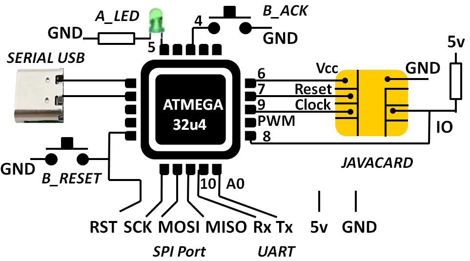
As shown in Fig. 1, the TLS-IM token comprises a Java Card (J3R180, Java Card 3.0.5, 85 KB flash, 3 KB SRAM) and an ATmega32U4 RISC microcontroller clocked at 16 MHz. The microcontroller includes 32 KB flash, 2.5 KB SRAM, 1 KB EEPROM, and a USB 2.0 full-speed/low-speed interface.
The Java Card is connected to the microcontroller through a five-wire ISO 7816 interface (Vcc, GND, reset, clock, and I/O). Two communication interfaces are available: USB serial and UART. USB serial supports laptops and smartphones with USB On-The-Go (OTG). The UART interface is used for SRAM-PUF measurements. We observed that USB serial initialization occupies most of the available SRAM after connection to a USB port and therefore alters the SRAM contents following power-up.
The user interface comprises an acknowledgment LED (A_LED) and two buttons: reset (B_RESET) and acknowledgment (B_ACK). A blinking A_LED signals that B_ACK must be pressed. Pressing B_RESET and B_ACK simultaneously reboots the device in administrator mode, in which all implemented commands are available.
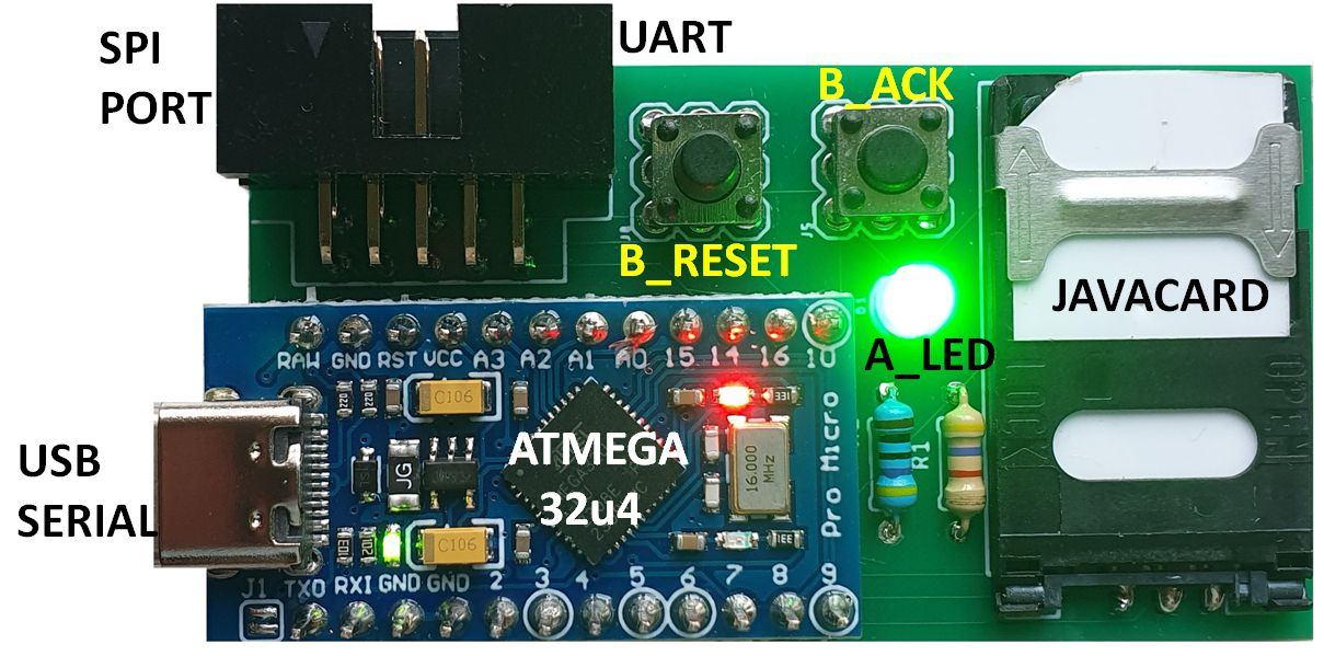
Figure 2 shows the experimental token, including an Arduino Pro Micro ATmega32U4 board, a 2FF SIM socket, two buttons, an LED, and a ten-pin serial programming interface (SPI) connector. The connector provides the RST, SCK, MOSI, and MISO signals used to program the microcontroller, as well as power and UART access.
B. Software
| Command | Description | Ch. | Ack. | Admin. |
|---|---|---|---|---|
| f | Dump 1 KB SRAM | 1–2 | No | No |
| bmac SEED | Time-stamped bijective MAC | 1 | No | No |
| on | Power on SE | 1 | No | No |
| off | Power off SE | 1 | No | No |
| user PIN | Power on SE and send PIN | 1 | No | No |
| binder DATA | Compute binder | 1 | No | No |
| derive DATA | Compute derive | 1 | Yes | No |
| getpk | Read SE public key | 1 | No | No |
| getcert | Read SE certificate | 1 | No | No |
| auth DATA | Authenticate SE | 1 | No | No |
| A DATA | Send APDU to SE | 1 | No | Yes |
| ewrite ADR DATA | Write EEPROM | 1 | No | Yes |
Fig. 3. Main commands supported by the TLS-IM token.
The token firmware was developed with the Arduino integrated development environment (IDE). A dedicated ISO 7816 library [11] drives the secure element. The firmware supports two serial channels (channel 1: USB serial; channel 2: UART), user and administrator modes, and commands requiring confirmation through the B_ACK button.
The firmware provides a command-line shell that parses ASCII commands received over the serial interfaces (Fig. 3). Channel 2 is used to read SRAM contents for PUF operations; channel 1 processes other commands. User mode supports the bMAC algorithm, the TLS-IM binder and derive operations (the latter requiring B_ACK confirmation), and smart-card activation with a PIN. Three commands—getpk, getcert, and auth—support secure-element authentication.
Administrator mode is entered by pressing B_RESET and B_ACK simultaneously. It enables the apdu command for exchanging ISO 7816 APDUs with the secure element, including for TLS-PSK configuration and Java Card application deployment. It also enables ewrite, which controls EEPROM write operations.
IV. SECURE ELEMENT
The secure element stores the pre-shared key (PSK) and executes the binder and derive operations. The measured execution time for these operations is approximately 100 ms. Incorrect PSK contents may cause a denial of service (DoS). Two administration requirements must therefore be considered: secure application deployment and authentication, and secure PSK storage.
A. TLS-IM Application Deployment
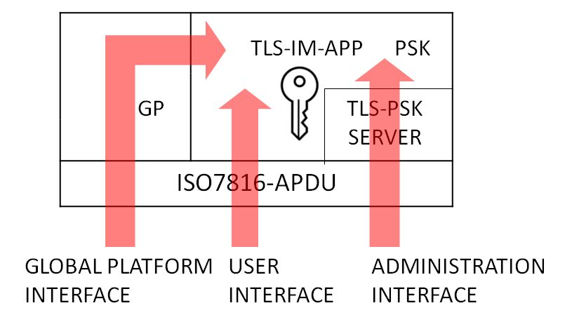
Many secure elements support GlobalPlatform (GP) protocols for secure application deployment. These mechanisms use symmetric secrets (128 bits in this implementation) from which encryption and integrity keys are derived. Because GP exchanges use APDUs (Fig. 4), administrator mode provides a transparent APDU bridge.
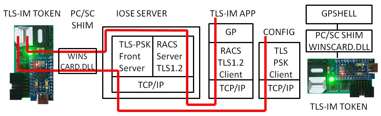
Open-source tools such as GPSHELL [12], which use the PC/SC API, can operate through a software shim (for example, a Windows WINSCARD.DLL implementation) translating PC/SC calls to the USB serial channel (Fig. 5, right). A similar shim enables the TLS-IM token to connect to an IoSE server [10] (Fig. 5, left).
B. TLS-IM Application Configuration
Upon instantiation, the TLS-IM application generates a public/private key pair on the secp256k1 elliptic curve. As described in [13], it also hosts an internal TLS-PSK server initialized with a provider PSK (Provider-PSK) for administration. The server is associated with a Secure Element Name (SEN) [10].
An IoSE server [10] supports TLS-IM tokens through PC/SC shims and exposes two TLS-protected network interfaces. The first supports a Remote APDU Call Secure (RACS) daemon, typically for GlobalPlatform management. The second is a front-end TLS-PSK interface connected to a named back-end TLS server, such as the TLS-IM token.
The internal TLS-PSK channel supports two administrative operations:
reading the secure element public key and forwarding a certificate signed by a certification authority; and
configuring the TLS-IM pre-shared key.
C. TLS-IM Application Authentication
In user mode, three commands support secure-element authentication:
getpk reads the secure element public key;
getcert reads the secure element certificate; and
auth DATA computes an ECDSA signature over DATA using the secure element private key.
V. SECURE ELEMENT PROCESSOR (SEP) AUTHENTICATION
SEP authentication is intended to detect counterfeit microcontrollers by identifying and authenticating the device incorporated into the TLS-IM token.
A. SRAM PUF and SRAM dPUF
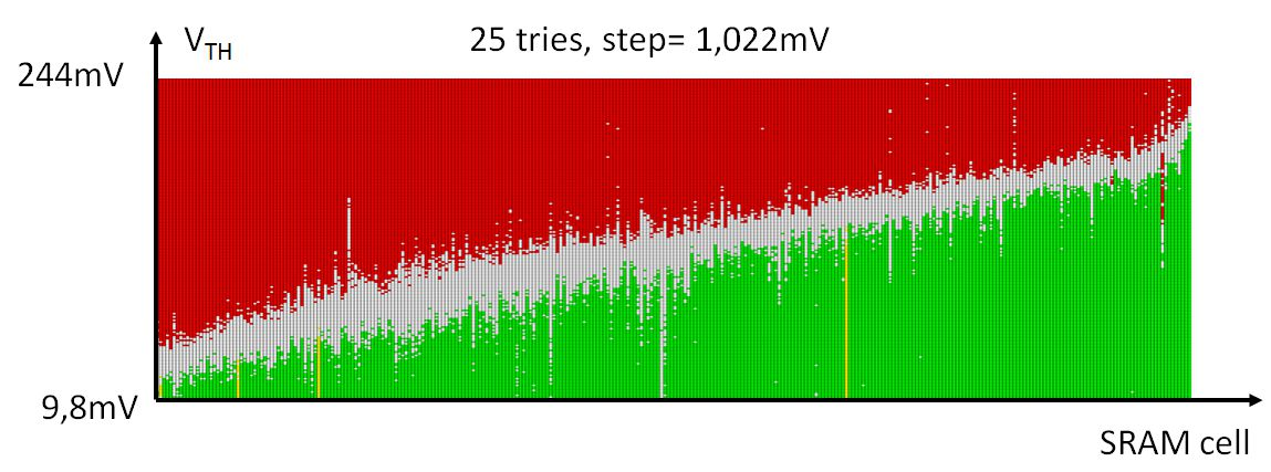
Microcontroller SRAM consists of memory cells built from six CMOS transistors forming two cross-coupled inverters. At power-up, many cells assume a stable value because of manufacturing asymmetries, whereas others have variable contents; this behavior is known as an SRAM PUF. As discussed in [14], [15], differences in capacitance and supply-voltage rise time may cause some cells to flip between stable values. Such cells can switch between zero and one depending on the voltage ramp. Flipping is not observed for slow rises (below 10 V/s) but can occur for rises of approximately 100 V/s. Each cell may exhibit a characteristic voltage threshold (VTH), measured here using ramp-and-square power-up signals with different knee voltages (VK; Fig. 7).
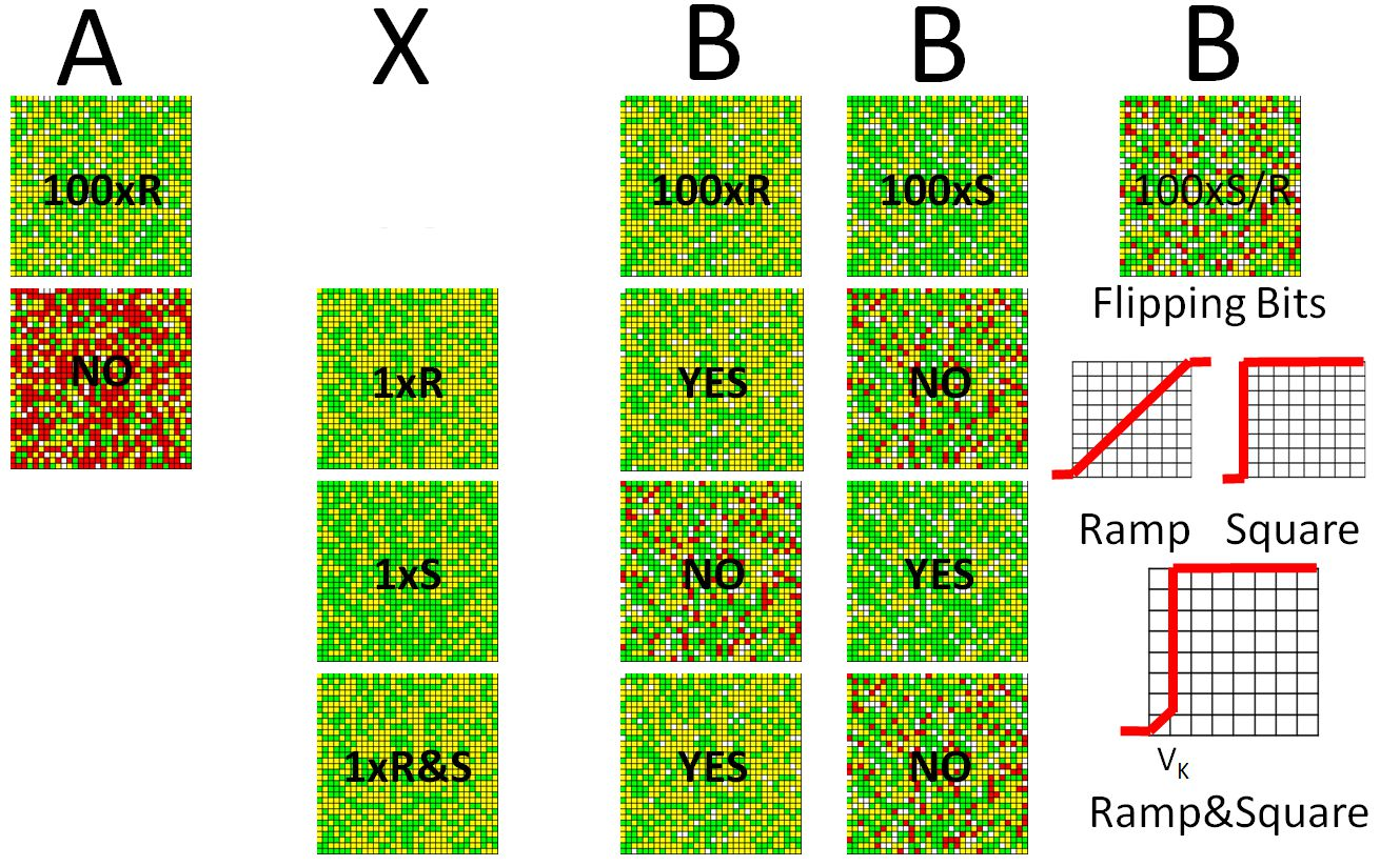
Three power-up waveforms are used: square (S, approximately 1500 V/s), ramp (R, 5 V/s), and ramp-and-square (R&S, with VK = 625 mV). In the reported experiment, square-wave power-up produces flipping bits. The proposed dynamic PUF (dPUF) relies on the microcontroller being unable to distinguish S from R&S excitation. Random selection of these waveforms yields SRAM-PUF responses that malicious firmware cannot reliably predict, even if reference PUF bits are known.
B. SEP Enrollment and Authentication
A dedicated power generator based on an ATmega2560 Arduino (16 MHz), a 12-bit MCP4725 digital-to-analog converter, and an LM358P operational amplifier supplies the token. The amplifier can sink approximately 40 mA. The generator firmware produces four voltage samples per millisecond, supporting voltage rise rates between approximately 5 and 1500 V/s. After power-up (P), 1 KB of SRAM is read through the serial interface.
The power-up procedure is repeated n times (Pn). Three classes of SRAM cells are identified (Fig. 6): always zero (Z, yellow), always one (O, green), and noisy (N, white), which may hold either value. Thus, M = O ∪ Z ∪ N.
The stable domain D is defined as D = O ∪ Z.
To compare two SRAM contents, M1 and M2, we define:
– the common domain: CD = D₁ ∩ D₂ = M₁,₂ ∪ F₁,₂;
– the matching-bit set: M₁,₂ = (O₁ ∩ O₂) ∪ (Z₁ ∩ Z₂);
– the flipping-bit set: F₁,₂ = (O₁ ∩ Z₂) ∪ (Z₁ ∩ O₂);
the similarity factor Sf = #M1,2 / #CD, where # denotes set cardinality. Sf is used as the device-authentication metric and is approximately 0.99 for matching measurements.
Matching bits (Fig. 6) are shown in yellow or green; flipping bits are red, and noisy bits are white.
For a given microcontroller, the flipping bits belong to a common domain determined by the S and R power-up waveforms. Their values may fall in O or Z depending on whether S, R, or R&S excitation is applied.
Device k is authenticated by comparing a single power-up response P1,k with reference responses Pn,i obtained from device i. An incorrect device produces approximately 50% mismatching bits, whereas the genuine device produces almost none (Sf > 0.99).
For two distinct devices i and k, comparison of Pn,i and Pn,k yields approximately 50% mismatching bits in the common domain (measured Sf = 0.494; Fig. 8).
For the same device, comparing responses Pn collected with square-wave power-up against responses P′n collected with ramp or ramp-and-square power-up identifies the flipping bits (Fig. 9).
| Device | Domain | Zero | One | Flipping |
|---|---|---|---|---|
| #10 | 3873 | 2162 | 1711 | 228 |
| #11 | 3867 | 1963 | 1904 | 182 |
| Common domain | 3658 | 1045 | 807 | — |
Fig. 8. Common-domain comparison for two devices based on 100 reference measurements; SRAM sample size: 4096 bits (512 bytes).
| Signal | Common Domain | Zero | One | Flip ping | Sf | Ma tch |
|---|---|---|---|---|---|---|
| S – R100 | 3873 | 1723 | 1699 | 451 | 0,884 | no |
| S – S100 | 3591 | 1506 | 2084 | 1 | 0,999 | yes |
| RS- R100 | 3873 | 2162 | 1708 | 3 | 0,999 | yes |
| RS- S100 | 3591 | 1503 | 1748 | 340 | 0,905 | no |
Fig. 9. Authentication of device #10 with square and ramp-and-square power-up signals; SRAM sample size: 4096 bits (512 bytes).
VI. SOFTWARE ATTESTATION
Firmware integrity is a major concern, particularly in the supply chain. Malicious firmware may enable man-in-the-middle (MITM) attacks. The time-stamped bijective MAC (bMAC_TS) method is a software-based remote-attestation approach [17], [18]. It employs a prover (the token) and a verifier, which sends a challenge and checks the returned response.
A. Time-Stamped Bijective MAC (bMAC_TS)
For a memory of size m (including flash, EEPROM, and SRAM), bMAC computes a memory fingerprint using a hash function h, such as SHA-256 or Keccak-256, over bytes visited according to a permutation P.
bMAC = h(A(P(0)) || A(P(1)) || … || A(P(m − 1)))
Here, A(x) denotes the byte stored at address x. The computation time (CT) is returned together with the bMAC value.
Working in the multiplicative group Z/pZ, where p > m is a safe prime of the form p = 2q + 1, q is a Sophie Germain prime, and p ≡ 7 (mod 8), the permutation P is defined as follows:


The generators gk in Z/pZ are defined by:

The number of possible permutations is (p−1)(q−1)², approximately m³/4 (2⁴³ for a 32 KB memory). Hence, storing all bMAC responses (approximately 2⁴³ × 32 bytes) in token memory is infeasible. Malicious firmware might nevertheless attempt a memory-copy attack using a genuine memory image. To help detect such attacks, the computation time is measured using an internal timer derived from the 16 MHz microcontroller clock (16 MHz / 64). Stopping and restarting the timer introduces timing uncertainty on the order of 4 µs per operation.
B. Enrollment and Authentication
The TLS-IM implementation uses the prime p = 36887 (32 K + 2.5 K + 1 K = 36352 memory bytes). A positive 31-bit integer passed to the bmac command seeds a pseudorandom generator [19], which derives s1, g1, and g2. Keccak-256 is used to hash the entire flash and EEPROM contents and part of SRAM, including the Keccak-256 context. Although EEPROM is not otherwise used by the application, the ewrite command can modify its contents to hinder replay of a copied memory image. Similarly, unused flash storage is filled with pseudorandom bytes in the firmware image.
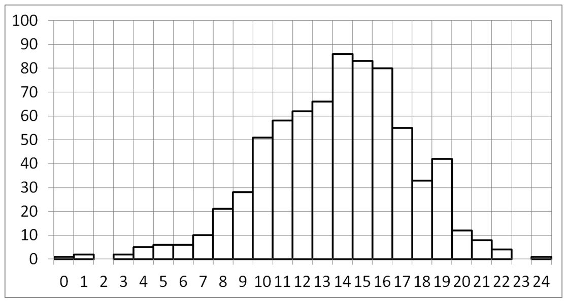
Repeated bmac commands with different seeds produce a table indexed by seed, containing bMAC values and computation times (CTs). The measured CT distribution is approximately normal (Fig. 10). Across 722 trials, using a timer resolution of 4 µs, the minimum count was 6,762,590, the maximum 6,783,464, the mean 6,774,474 (approximately 27 s), and the standard deviation 3,005 counts (approximately 12 ms). Assuming most measurements fall within three standard deviations, the estimated timing entropy is approximately 13 bits.
VII. CONCLUSION
This paper presented a three-factor TLS-IM authentication token comprising a microcontroller, a secure element, an LED, and two push buttons. Its software was developed with the Arduino IDE [20] and the Oracle Java Card 3.0.5 Software Development Kit.
The secure element is assumed to originate from a trusted manufacturer. GlobalPlatform keys protect application loading, application-provider asymmetric keys support software authentication, and a provider-initialized PSK secures the TLS-PSK administration channel.
The microcontroller is authenticated through a dynamic SRAM PUF (dPUF), while its firmware integrity is evaluated using bMAC_TS attestation.
Three-factor authentication combines possession of the token, entry of a PIN, and explicit push-button authorization of cryptographic operations.
The design demonstrates how open hardware and software components can be combined with secure-element cryptography and hardware/software verification mechanisms for applications requiring trusted multi-factor authentication.
REFERENCES
- [1]A. A. S. AlQahtani, Z. El-Awadi and M. Min, "A Survey on User Authentication Factors," 2021 IEEE 12th Annual Information Technology, Electronics and Mobile Communication Conference (IEMCON), Vancouver, BC, Canada, 2021, pp. 0323-0328, doi: 10.1109/IEMCON53756.2021.9623159.
- [2]Ometov, A., Bezzateev, S., Mäkitalo, N., Andreev, S., Mikkonen, T., & Koucheryavy, Y. (2018). "Multi-factor authentication: A survey". Cryptography, 2(1), 1.
- [3]V. Lomme, “An Overview of the Security of Some Hardware FIDO(2) Tokens,” Hardwear.io Security Trainings and Conference, Netherlands, October 24–28, 2022. https://hardwear.io/netherlands-2022/presentation/security-of-Hardware-FIDO(2)-tokens.pdf
- [4]Thomas Roche, Victor Lomné, Camille Mutschler, Laurent Imbert. "A Side Journey To Titan: Revealing and Breaking NXP’s P5x ECDSA Implementation on the Way." USENIX Security 2021, USENIX Security Symposium, Aug 2021, Virtual, Canada. pp.231-248.
- [5]U. Guin, K. Huang, D. DiMase, J. M. Carulli, M. Tehranipoor and Y. Makris, "Counterfeit Integrated Circuits: A Rising Threat in the Global Semiconductor Supply Chain," in Proceedings of the IEEE, vol. 102, no. 8, pp. 1207-1228, Aug. 2014, doi: 10.1109/JPROC.2014.2332291.
- [6]T. M. Jurgensen and S. B. Guthery, Smart Cards: The Developer’s Toolkit. O’Reilly.
- [7]Z. Chen, Java Card Technology for Smart Cards: Architecture and Programmer’s Guide. Addison-Wesley, 2000.
- [8]IETF Draft, "Identity Module for TLS Version 1.3", draft-urien-tls-im-09.txt, July 2023
- [9]P. Urien, "Innovative TLS 1.3 Identity Module for Trusted IoT Device," 2021 IEEE 18th Annual Consumer Communications & Networking Conference (CCNC), Las Vegas, NV, USA, 2021, pp. 1-4, doi: 10.1109/CCNC49032.2021.9369656.
- [10]P. Urien, "On Line Secure Elements: Deploying High Security Keystores and Personal HSMs," 2023 International Conference on Computing, Networking and Communications (ICNC), Honolulu, HI, USA, 2023, pp. 450-455, doi: 10.1109/ICNC57223.2023.10074066.
- [11]ISO 7816 Library for Arduino. https://github.com/purien/SCLIB-ARDUINO
- [12]GlobalPlatform Shell (GPSHELL). https://github.com/kaoh/globalplatform
- [13]IETF Draft "Internet of Secure Elements", draft-urien-coinrg-iose-07.txt, IETF Draft, April 2023
- [14]Elshafiey, A. T., Zarkesh-Ha, P. and Trujillo, J. (2017). The effect of power supply ramp time on SRAM PUFs. 2017 IEEE 60th International Midwest Symposium on Circuits and Systems (MWSCAS). https://doi.org/10.1109/MWSCAS.2017.8053081.
- [15]Urien, P. (2020). Innovative Dynamic SRAM PUF Authentication for Trusted Internet of Things. 16th International Conference on Wireless and Mobile Computing, Networking and Communications (WiMob). https://doi.org/10.1109/WiMob50308.2020.9253432.
- [16]Sigurd Frej Joel Jørgensen Ankergård, Edlira Dushku, Nicola Dragoni, "State-of-the-Art Software-Based Remote Attestation: Opportunities and Open Issues for Internet of Things", Sensors 2021, 21(5), 1598; https://doi.org/10.3390/s21051598
- [17]Seshadri, A., et al (2006). SCUBA: Secure Code Update By Attestation in sensor networks. WiSe '06: Proceedings of the 5th ACM workshop on Wireless security. https://doi.org/10.1145/1161289.1161306
- [18]Urien, P. (2020). Proving IoT Devices Firmware Integrity With Bijective MAC Time Stamped. IEEE 6th World Forum on Internet of Things (WF-IoT). https://doi.org/10.1109/WF-IoT48130.2020.9221395.
- [19]Park, S.K., Miller, K.W, (1998) Random Numbers Generators: Good Ones Are Hard to Find. Communication of ACM , Volume 31, Number 10, pp1192-1201.
- [20]https://github.com/purien, seen November 2023